ELE1001 — Digital Systems & Embedded
BCD Keypad Display & Pill Bottling System
A complete three-stage automated system combining Arduino-based user input with discrete digital logic for accurate pill counting and bottling control. Demonstrates microcontroller integration with TTL components in a real-world industrial application.
General Objective
The objective of this project is to design an embedded digital system capable of reading a user-defined quantity through a 4×4 keypad, displaying that value in BCD on two seven-segment displays, and using this value to control an automated pill bottling process. The system must be reliable, deterministic, and compatible with downstream digital logic, combining discrete logic components with Arduino-based optimization for a modular and maintainable architecture.
System Architecture: Three Stages
User Input & Display
Arduino manages keypad scanning, BCD conversion, and seven-segment display control entirely in software.
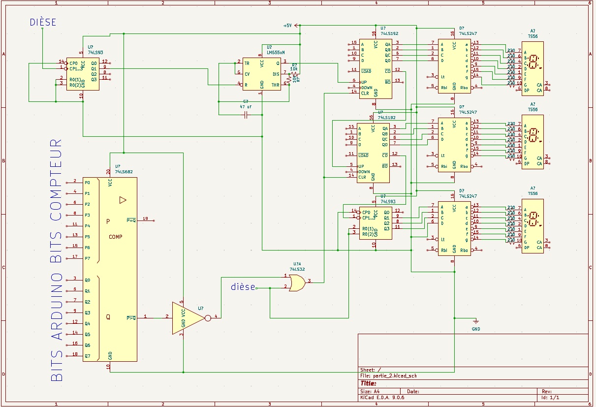
Pill Counting
Cascaded BCD counters and magnitude comparator detect when the correct number of pills has been counted.
Bottle Counting
Modulo-8 counter tracks filled bottles (0–7) with seven-segment display and automatic wraparound detection.
Stage 1: User Input & Display (Arduino)
Keypad Reading
A 4×4 matrix keypad serves as the human-machine interface. The Arduino performs matrix scanning:
- •Columns are driven LOW one at a time
- •Rows are read using INPUT_PULLUP configuration
- •A key is detected when a row reads LOW while its column is active
Key Design Decision:
The system detects key release, not key press. This naturally eliminates switch bounce and prevents repeated inputs when a key is held—a crucial reliability improvement.
Conversion to BCD
When a numeric key (0–9) is released:
- •The key is converted to its BCD representation
- •The system automatically alternates between units and tens digits
- •An internal state variable handles this alternation
This design allows intuitive two-digit entry without additional confirmation steps.
BCD Output Generation
The Arduino drives eight dedicated GPIO pins:
- •Naturally wraps around after 7 (no extra detection logic needed)
Display of Bottle Count (74LS247)
The three-bit counter output drives a 74LS247 BCD-to-seven-segment decoder, which controls a dedicated seven-segment display showing the number of filled bottles (0–7). This provides real-time visual feedback on production progress.
Global Reset Using #
Pressing the # key resets:
- •Both pill counters
- •The bottle counter
- •The display system
This guarantees a clean return to a known and stable initial state for the next production cycle.
Why Arduino Was Chosen
Migrating the display and keypad logic to an Arduino provided significant engineering advantages over a purely discrete implementation:
Reduced Hardware Complexity
Eliminates dozens of debounce capacitors and logic gates
Elimination of Debounce Circuits
Release-detection algorithm handles bounce inherently
Improved Signal Stability
Software control ensures clean, predictable BCD outputs
Easier Future Modifications
Firmware changes require no PCB redesign
Better Synchronization
Precise timing control for Z and # signal pulses
TTL Compatibility
Direct BCD outputs work seamlessly with discrete logic
Project Resources & Media
Final Result
The complete system delivers a robust, production-ready solution for automated pill bottling:
- →Intuitive user input via matrix keypad
- →Stable, synchronized BCD output signals
- →Accurate pill counting from 0 to 99
- →Automatic bottle completion detection
- →Modular bottle tracking (0–7 bottles per box)
- →Clean, predictable state resets
The design respects digital logic principles, modularity, and real-world reliability constraints, demonstrating professional engineering practice in embedded systems.